- Home
- Product Categories
- IMU
- SparkFun Triple Axis Accelerometer and Gyro Breakout - MPU-6050

SparkFun Triple Axis Accelerometer and Gyro Breakout - MPU-6050
The MPU-6050 is a serious little piece of motion processing tech! By combining a MEMS 3-axis gyroscope and a 3-axis accelerometer on the same silicon die together with an onboard Digital Motion Processor™ (DMP™) capable of processing complex 9-axis MotionFusion algorithms, the MPU-6050 does away with the cross-axis alignment problems that can creep up on discrete parts.
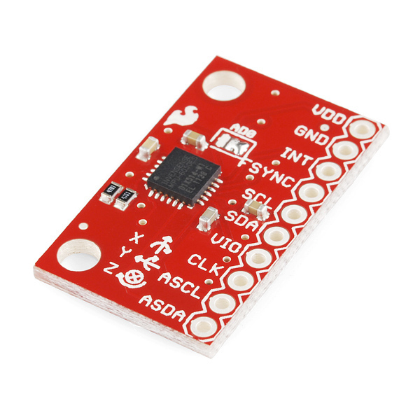
Our breakout board for the MPU-6050 makes this tiny QFN package easy to work into your project. Every pin you need to get up and running is broken out to 0.1" headers, including the auxiliary master I2C bus which allows the MPU-6050 to access external magnetometers and other sensors.
Having a hard time picking an IMU? Our Accelerometer, Gyro, and IMU Buying Guide might help!
- I2C Digital-output of 6 or 9-axis MotionFusion data in rotation matrix, quaternion, Euler Angle, or raw data format
- Input Voltage: 2.3 - 3.4V
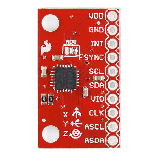
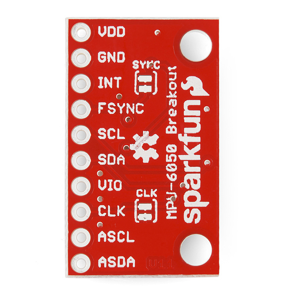
- Selectable Solder Jumpers on CLK, FSYNC and AD0
- Tri-Axis angular rate sensor (gyro) with a sensitivity up to 131 LSBs/dps and a full-scale range of ±250, ±500, ±1000, and ±2000dps
- Tri-Axis accelerometer with a programmable full scale range of ±2g, ±4g, ±8g and ±16g
- Digital Motion Processing™ (DMP™) engine offloads complex MotionFusion, sensor timing synchronization and gesture detection
- Embedded algorithms for run-time bias and compass calibration. No user intervention required
- Digital-output temperature sensor
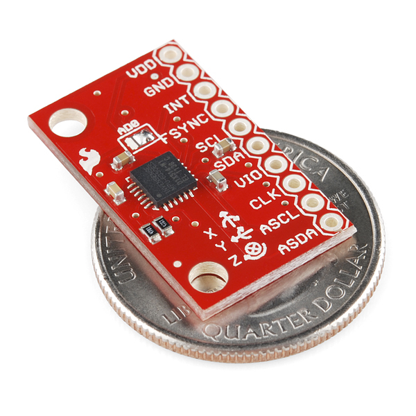
- 1 x 0.6 x 0.09" (25.5 x 15.2 x 2.48mm)
- Schematic
- Eagle Files
- Datasheet (MPU-6050)
- Example Code
- I2Cdevlib Page
- GitHub
SparkFun Triple Axis Accelerometer and Gyro Breakout - MPU-6050 Product Help and Resources
Hackers in Residence - Sound and Motion Reactivity for Wearables
October 3, 2014
How to consciously wear light-up and and sound reactive clothing.
VIO pin
If you are seeing this as the output when using I2C, then the sensor is not connected correctly. http://www.i2cdevlib.com/forums/topic/8-mpu6050-connection-failed/ :
Initializing I2C devices...
Testing device connections...
MPU6050 connection failed
a/g: 0 0 0 0 0 0
a/g: 0 0 0 0 0 0
a/g: 0 0 0 0 0 0
a/g: 0 0 0 0 0 0
a/g: 0 0 0 0 0 0
.
.
.
You need to have this basic connection: VDD - Arduino 3.3v GND - Arduino GND INT - Arduino digital pin 2 FSYNC - unconnected SCL - Arduino SCL dedicated pin SDA - Arduino SDA dedicated pin VIO - Arduino 3.3v CLK - unconnected ASCL - unconnected ASDA - unconnected
Core Skill: Soldering
This skill defines how difficult the soldering is on a particular product. It might be a couple simple solder joints, or require special reflow tools.
Skill Level: Noob - Some basic soldering is required, but it is limited to a just a few pins, basic through-hole soldering, and couple (if any) polarized components. A basic soldering iron is all you should need.
See all skill levels
Core Skill: Programming
If a board needs code or communicates somehow, you're going to need to know how to program or interface with it. The programming skill is all about communication and code.
Skill Level: Competent - The toolchain for programming is a bit more complex and will examples may not be explicitly provided for you. You will be required to have a fundamental knowledge of programming and be required to provide your own code. You may need to modify existing libraries or code to work with your specific hardware. Sensor and hardware interfaces will be SPI or I2C.
See all skill levels
Core Skill: Electrical Prototyping
If it requires power, you need to know how much, what all the pins do, and how to hook it up. You may need to reference datasheets, schematics, and know the ins and outs of electronics.
Skill Level: Noob - You don't need to reference a datasheet, but you will need to know basic power requirements.
See all skill levels
Comments
Looking for answers to technical questions?
We welcome your comments and suggestions below. However, if you are looking for solutions to technical questions please see our Technical Assistance page.
Customer Reviews
3.5 out of 5
Based on 8 ratings:
5 of 5 found this helpful:
Average 6DOF, convenient board though.
This is probably one of the easiest boards to hook-up and use, and the on-board DMP is pretty nice. That being said, I found the results from the MEMS accel and gyro on this guy to be pretty wildly inaccurate. Adding an external compass helped to rectify that a little but in that case you'd want to move up to the MPU 9150 break-out board instead as it's an all-in-one single die solution and easier to do than adding a compass as an afterthought to this board. I found a much more reliable MEMS 9DOF chip in the Bosch BNO055 chip thats even easier to use, though, and have been using that for my projects with better results. Hopefully Sparkfun will make a break-out board for that chip soon! Because of these things I only rated this board as "Okay" - it will generally work for you and it's easy to use, but there are much better chips for the price.
1 of 1 found this helpful:
A bit of a problem hooking it up.
A hookup guide would have been helpful. Many internet searches required before I got it working.
2 of 2 found this helpful:
Pretty good, but could be better considering the price
For a board of this price should be easier to use. I didn't see anything in the provided documentation from Sparkfun about having to connect the VIO line to a 3V3 source as an IO Reference voltage. This should be documented better. Also the should be a solder-able bridge to tie VIO to VDD so that on 3V3 systems an aditional wire doesn't need to be run. The one extra wire really should only be necessary with a 5V VDD. Also the addition of an LED again with a solder link to disable it would be very useful to help verify that the MPU-6050 is actually being powered.
1 of 1 found this helpful:
Easy I2C, with good performance for a tiny chip
The triple accel, triple gyro with internal temp sensor is why I bought this. Very thing you need for attitude sensing on a single chip. Communication via I2C was straight forward. Sparkfun should add a jumper however connecting VIO to the 3.3v, Once I figured that out (review above) everything worked fine.
1 of 1 found this helpful:
I ordered two, only one of them is working
As long as it is working (50% chance?), it is fine.
We're sorry to hear that! Please contact our technical assistance team and they can help you with this.
Very easy to set up and very durable
Plenty of code online for how to hook it up and retrieve data from it. Also very durable. I've done soldering of wires near it, heating it up with a heatgun (for nearby heatshrinks). Dropped tools on it and crashed my quadcopter but it survived all of that.
Why pay a premium for something undocumented?
~10 years ago when I was a student I bought from SparkFun because their boards were documented and tutorials provided. It justified the cost.
Using muscle memory I purchased this, which is (at most) $5 of chips soldered onto a tiny circuit board and sold for $30, figuring the student I was supporting could read the tutorials.
I was disappointed to see unrelated tutorials linked, no real tutorial, etc. I had to read the circuit diagram and google around to figure out how to wire it up. This is all fine, but then why am I paying $30 from SparkFun instead of $7.99 from other suppliers?
I need to re-train that muscle memory of mine and buy from someone else.
Hook up VIO to 3.3V!
Duh, I wasted time before finding this out from these reviews. Once done, there was no problem getting it communicating at 400kHz. I expect that information is available on the MPU datasheet, but I tend to like to dive in and get the thing talking asap.
For anyone using the MPU-6050 or MPU-9150 with I2Cdevlib, there is an official support forum for those devices when used with that library now available here:
http://www.i2cdevlib.com/forums/forum/2-mpu-6050-6-axis-accelerometergyroscope-invensense
It's a little easier to work with an endless comment threads here, and more open than the InvenSense forums (no draconian "no reverse-engineering allowed" terms of service). There are already answers up there to some of the questions here.
Thanks for sharing this info!
-------------------- Tech Support Tips/Troubleshooting/Common Issues --------------------
If you are seeing this as the output, you are not connecting to the sensor correctly http://www.i2cdevlib.com/forums/topic/8-mpu6050-connection-failed/ . Most likely VIO is not connected to the 3.3V pin.
They need to have this basic connection:
The interrupt pin is if you are using the MPU6050_DMP6.ino file https://github.com/jrowberg/i2cdevlib/blob/master/Arduino/MPU6050/examples/MPU6050_DMP6/MPU6050_DMP6.ino .
I2Cdevlib Support
"For anyone using the MPU-6050 or MPU-9150 with I2Cdevlib, there is an official support forum for those devices when used with that library now available here:
http://www.i2cdevlib.com/forums/forum/2-mpu-6050-6-axis-accelerometergyroscope-invensense
.. [it's] more open than the InvenSense forums (no draconian “no reverse-engineering allowed” terms of service). There are already answers up there to some of the questions here. - Jeff Rowberg "
Documents MPU-6050 datasheet link does not work!
Datasheet (Revision 3.4) and MPU-6050 Register Map and Descriptions documents can be obtained from: http://www.invensense.com/products/motion-tracking/6-axis/mpu-6050/
Got it to work just fine with my Uno, but I am having trouble getting it to work with the Pro Micro and/or Leonardo. From what I understand is that on the Uno the SCL and SDA pins are located on A5 and A4 whereas on the Leonardo it should be on D2 and D3 (the digital pins 2 and 3, not the atmega32u4 pins). The sample sketch for reading raw data uploads successfully, however, upon turning on the serial monitor, its completely blank. Does anyone have any ideas on how to get this to work on the Pro Micro or the Leonardo? Thank you!
Hi, pins 2 and 3 work for me but conflict with another device I am connecting to my micro. I am using the Sparkfun Pro Micro (ATMega32U4). Is there any way to change the pins used?
Did you use pullup resistors (4.7k)? Uno is normally very forgiving if you don't but the Micros normally need them
By any chance did you get this to work? I am trying to get the MPU to work with the Pro Micro and it just hasn't worked out. I tried both the D2 and D3 based SCL and SDA connections, but it just shows me a blank screen as well (just says "Trying to connect to MPU ....." Like you, I too got it to work with the Uno without much fuss.
Any help will be greatly appreciated.
Is the operation of this thing still locked up tight, away from hobbyist access?
I recall something about the whole "capable of processing complex 9-axis MotionFusion algorithms" meaning "capable if you're a big company and we decide to share the documentation with you".
And hobbyists were just able to get the raw sensor data (still neat) but not access the nice algorithms? Has that been remedied? Is this a magic IMU in a chip now? (minus compass)
Because if those algorithms are still not something we can use, I think Sparkfun needs to mention that in the description.
Check this Arduino sketch out for some recent progress (i.e. pushed out 10 minutes ago) on the DMP front:
MPU-6050 6-axis DMP-based Arduino sketch
Hopefully more to come before long.
Hi Jeff, Thanks so much for this awesome bit of work, it makes the difference between a hobbled curiosity and a useable tool for me. Hey, everything seems to be working really well for me with one exception. My z-axis accel consistently reads around +1700 at rest. Seems like an odd number (not 1g) and I know the output is supposed to have gravity removed. It responds as it should to movement (other than being off by 1700). Any ideas? Thanks!
Hi Jeff,
(Great Work!)
Were you able to use the DMP to perform the fusion of the mag measures?
Refards, V.
Thanks! And unfortunately there is no magnetometer fusion yet. The sketch I was working with was based directly on the 6-axis "Embedded MotionApps" code they used with the original MPU-6050 evaluation board, which only makes use of the accel/gyro measurements even though there is an AK8975 mag onboard.
I also have a MotionFit evaluation board though, which uses the MPU-9150, essentially an MPU-6150 with an AK8975 baked into the same chip. The sniffed DMP code for that should technically work with a discrete MPU/mag combination, with maybe a few tweaks. I haven't got that far yet though. And certainly it would take a little more effort to use any magnetometer besides the AK8975, such as the ever-popular HMC5883L. I hope to achieve that functionality at some point though.
Hi Jeff, maybe you can help me. I've been using your Arduino code with the Fio and Xbee and the MPU6050 of course and sending data to Processing. I'm rotating an object based on axis[0] from your code but what I'm finding is the value is going up from 0-6 and then climbing back down all on it's own without the sensor even moving. Am I doing something wrong, is there a way to fix this? Thanks for the great code and documentation!
Is it going back and forth between 0 and 6, or is it happening only at first? There is a ~8-second calibration routine that happens first when the DMP is enabled the first time. This is expected behavior and inherent in the DMP algorithm. There is also an issue with yaw/pitch/roll in my code (at the moment) where pitch and roll don't go above +/- 90 degrees when they should.
Hi Jeff. I am wondering if you have figured out the reason for the pitch/roll values not going above +/-90 degrees. I ran into the same issue when I mounted the IMU vertically. Any help would be appreciated.
EDIT (4/2/13): I think I found the issue in the code. It's in the MPU6050_6Axis_MotionApps20.h file. Where the yaw/pitch/roll is calculated (lines 644-653) it is impossible to get angles above +/-90 degrees because of trig function used (atan). Atan only provides values between -90 and +90 degrees hence why we can't get anything above that. Atan2 provides values between -180 and +180 degrees. I am working on changing it. I will post any updates.
Was it possible to implement Atan2 and provide values between -180 and +180 degrees?
Hey all,
Thanks for putting in all the hard work to make this sensor more accessible, Jeff!
Its almost an embarrasing question to ask, but I am trying to verify how the MPU6050 is connected physically. The wire library says SDA is on analog pin 4 and SCL is on analog pin5. I have VDD on the chip going to 3.3v, GND to GND and SCL and SDA going to 5 and 4 respectively. Is this correct? When I run the MPU6050_Raw sketch it says connection failed. Anyone have suggestions?
Side note: I accidentally connected VDD to 5v for a few seconds before realizing the chip required lower voltages. I'm praying to buddha, krishna, baby jesus, allah and the spirit of Ron Burgundy that I didn't damage the chip. Is there any way to test if I destroyed it or not?
Thanks all!
Hi! The problem is most likely a missing VIO connection. This is not obvious if you don't know it's required. Here are the typical connections for the SparkFun breakout, including the interrupt pin to work with the DMP example sketch:
Hi, sorry for my simple question but I read a lot the forum and i didn't find an answer. I've connected my sen1128 to arduino leonardo as you said and i correctly uploaded the example sketch. It seems that nothing works well. I see only the "on led" fixed green and on the serial monitor is just blank. It seems that there is a problem with communication. Is it necessary to define the port for I2C bus? Thank you! Regards, Manuel
Hi Manuel,
To be honest, I haven't worked much with the Leonardo yet, and I suspect the issue you are seeing has to do with that. I am not sure how to help at this point. Perhaps other have been able to work with it though, and may chime in here.
Hi Jeff, I solved! The SCL and SDA pins on Arduino Leonardo is digital 2 and 3 as reported on Wire Library at http://www.arduino.cc/en/Reference/Wire. Now I begin to have fun...
Bye, Manuel
Thank you Jeff anyway. I'm searching around but at the moment I didn'f found anything. Bye
#
I've been reading everything I can, moving past the compiling errors that I started with (learning along the way why I was getting them), and I have to foremost thank you for all the work you've put into documenting things.
That said, I can't for the life of me figure out how to switch SCL and SDA to a different line. I'm planning on using a baby orangutan, and I'm running through a level shifter (Sparkfun's one that's suitable for I2C comm), just to make sure I keep things safe for the sensor (though it seems like everyone here gets away with using the arduino on the sensor, but I don't want to mess up.)
In principle, I can use the baby orangutan pins that correspond with arduino analog 5 and 4 (in fact, I don't change anything, since I'm still using the arduino ide), but I expect there to be somewhere that I "set" what pins I'm using for SCL and SDA. But I cannot find that place.
As far as I can tell, the Baby Orangutan uses the same ATmega328P chip that the regular Arduino Uno uses. In this case, the I2C lines are fixed to A4/A5. There is no way to reassign them unless you move away from the hardware I2C/TWI bus, which is not usually a good idea. On the 328P, there is only one choice.
Functionally speaking, this part of the communication is handled in the Wire library, or one of a few custom TWI implementations like the I2C Master Library or Fastwire. I2Cdev only has Wire support for now, but I really need to add Fastwire.
Ok! Jeff, I now have some succinct questions I was hoping I could ask you, or anyone else who might be able to help me. I have everything running on the Baby Orangutan, and am a happy kid.
That said, I am not sure my calculations are super accurate, and want to make sure my settings are optimized for a tilt-sensing application.
1) When I do the demo code for pitch/roll/yaw, I notice the values are only given to 2 decimal digits. I'm a bit confused, because I don't see them being truncated anywhere. I only need them to two decimal points, but i was hoping to ensure it wasn't that I was killing the data early. 2) I want to have my Accelerometer set to +/-2g. All my trawling has taught me that these are the relevant things:
So I'm not totally clear when SEL_LENGTH does, and I don't understand if it's AFS_SEL_BIT that determines the range, or FS_2, or both. It seems there are also some things that I could optimize to reduce the sampling rate, since I don't need more than a sample a second, but it might be beyond me. I know a lot of people are making much cooler applications with this, but I'm starting out with a tilting precision instrument xD. The registry map files I could find seem to be useful, the only bits (heh, a pun) I could learn from where the places where you commented in your code.
Wow, I really need to set up a forum on i2cdevlib. :-)
Typically you don't want to change any of the #defined values, but instead effect different behavior with class methods and different parameters. The _ACCEL_FS_2 is the value which represents +/- 2g, correct. The _AFS_SEL_BIT is the bitfield position in the config register. Changing this will have undesirable results. The _AFS_SEL_LENGTH is the number of bits which the _AFS_SEL field takes. The register map from InvenSense says this field is 2 bits wide, hence the value 2. Changing this will also have undesirable results. You are probably really looking for the "setFullScaleAccelRange()" method. However, the power-on value of the module is already +/- 2g, so this is probably unnecessary.
Incidentally, the data from the DMP is calculated internally on the module, and I'm not sure that setting the full scale accel range even has an effect on how it works. If you're using the DMP6 example sketch, the 2-decimal-place rounding is due to the AVR's handling (or possibly the Serial.print() function's handling) of float variables. The original data from the DMP is coming across as four quaternion elements, represented as signed ints in the range of [-16384, 16384] and then scaled to floats in the range of [-1.0, 1.0]. These values are computed into angles (no idea exactly how, I just found some code that worked). Any precision loss is going to happen there, if at all.
I hope this helps!
hi Jeff! I am making a quadcopter with MPU6050 and PIC16F877.But I dont know how can ı connect each other.and I use CCS C as software but I dont do it too.This mpu6050 sensor works with I2C PROTOKOL. can Anyone help me about this issue. Wait your helps.. please..!
Thanks Jeff! That information definitively helps. Eventually someday setting up a forum might help, at least I feel cognizant that if you're the only name associated then you probably get a fairly substantial amount of questions, and I feel a bit guilty :p.
For some crazy reason, I think I was still getting sensible results with my messed up AFS_SEL_BIT and SEL_LENGTH values. I'm going to have to double check that later, but for now I'll proceed with the rest of my code while using your suggested values. I definitively am getting sensible values right now, with your numbers.
I get pretty decent tilt angle results, and again, thank you because I know I couldn't have set up the accelerometer or I2C comm by myself. I believe my values are correct +/- 0.5 degrees. Which is not quite as good as i expected, but still great! I'm a little surprised at how long it takes the measurements to stabilize, so if that's not a fault of my code, I'm going to look into what else I might to do in the MPU setup to fix it. Basically it takes me 3-9 seconds after I rotate my sensor to get a stable reading on the tilt sensor (I also wait 30 seconds after starting the sensor just to make sure everything is happy. It seems to jump a little in the beginning.)
For what it's worth, the line I found where it defines TWBI to be based on "160000 / khz" instead of CPU_FREQ/TWI might actually be considered a bug. I'm just not sure why at one point it seems to define TWBI as a variable based on processor frequency and I2C frequency, and at another point it just plugs in the expected 16mhz and expected 100khz speeds. I could be completely wrong, though; I apologize. But I have confirmed that changing that seems to be what fixed my I2C communication.
Hello again! This is me, at the end of the day. I spent the whole day minus a few hours that I was called for something else, trying to troubleshoot this situation. I spent ages double checking my logic level converter and wiring on the breaboard (perf board- soldered. All good connections.)
I could not manage to implement I2C on the orangutan, though I managed to get SPI working without a hitch (well, after I got through the newb hitches involved in that). So I would get a "device failed to initialize" which had me for ages double check the wiring.
I had an UNO with a burnt ftdi chip that I couldn't use the standard uno programming for, so I uploaded your code as if the UNO was a baby-orangutan. I got garbage on the serial monitor, which I assume is because the code is being compiled for the 20Mhz chip, and it's actually running at 16mhz. So I changed is so the code baud rate is running at 115200*20/16, and the serial monitor is set to 115200, and bingo it works. The thing is that I2C also connects properly.
So there is one of two things going on.
Either A) I'm not connecting the right pins on the orangutan, though I truly think I am connecting things correctly. I have PC5 connected to SCL, and PC4 connected to SDA, (and VIO to 3.3, and VDD to 3.3v). I have interrupt connected to PD2.
B) The I2C library isn't set for the 20mhZ speed of the orangutan. This is the one I will try to investigate, though I am nooby.
I do get information from the test program, jerry rigged as I described through the orangutan. I can't be sure my information isn't junk, because I get semi-logical information, but I also have a fifo overflow alerts every so often. So I wonder if I can't slow things down.
I'm going to keep playing, but as sort of indicated, I'm a newb and not sure this isn't some super-obvious problem. I am grateful though for you sort of enabling someone like me to play with this. It's pretty exciting. I'm a mechanical engineering student but I've had a wonderful love-hate experience with these accessible electronics. First it's 8 hours of hell, then it's 30 seconds of euphoric joy, when something actually works :p.
FIFO overload was fixed by changing the last 0x01 on the MPU motions file (as it said in the comments) to 0x09. 20khz instead of 100khz.
I still have to solve the situation so I can get this running on the baby orangutan. I'll make sure that I spread ze info when I'm done.
Well, I made a noble attempt (I say noble because it was tragic), but that didn't work out too far. But I think I saw some more references online that the Baby Orangutan needs some settings changed to account for the 20mhz when using I2C libraries. Yet, I'm not really sure. I managed to attempt to make new versions of Wire.H and Twi.h that I called Wire20.h and Twi20.h (and their CPP files), plug that into my sketch folder, and change all references to twi and wire to their respective 20 version, but things don't quite work as I intended and so I just broke the code. For now I'll try to go back to base one. I'll also try to stop detailing the step-by-step story of my project, because I didn't realize it would get to be such a long monologue.
EDIT: It's 1:30am, and I have it running on the arduino. I'm not sure if I just identically fixed it, or properly fixed it. But in I2Cdev there are two things to change. One is the CPU_FREQ to equal "20..." instead of "16..." where the "..." represents the rest of (six zeros, and L, or something like that.) The other is somewhere in I2Cdev is defined TWBR as something like (CPU_FREQ/TWI_FREQ)-16)/2, however elsewhere it ALSO defines TWBR as (16000/Khz)-16/2 and if you change that 16000/Khz to CPU_FREQ/TWI_FREQ it works.
Either that, or it's simply because I remade my wiring harness.
Woah, thank you Jeff.
I should have realized I2C was a hardware implemented thing. I'll switch over to the appropriate pins in the morning (I didn't get far enough today to even test the code.)
Yes, Baby Orangutan uses the same chip, the primary difference is that it's running at 20mHz, not 16mHz (messes up a few libraries), and a few pins are tied up connected to a dual motor driver. I'm primarily using the orangutan because I'm using that same board in another project, and I want to avoid changing too many variables each time I'm working on a new project. (Interfacing with the accelerometer, though you've done the real work, is still a relatively big trick for me.)
That worked great, thanks!
Hi, I also did this today that I accidentally connected VDD to 5V. And the accl and gyro data I read are all zeros no matter how I move it. Does that mean I destroyed the sensor? Thanks!
Look at the page for the mpu6050 chip. there's links to code examples and pretty much what you need in the comments. also datasheets are for the most part posted at invensense.com on the public site and what is not there is available to anyone who registers as a developer.
Good luck. Sparkfun will reply in the comments "We know! It's awful! They should really release that documentation!"
But fix their description to make it clear that that functionality is NOT built in? Never! Why, if people knew that, they might not buy this board! Much better to buy it and be frustrated by a misleading description, as long as Sparkfun gets paid.
The problem is that the MPU-60X0 chip has instruction memory inside and the InvenSense example code loads this memory with instructions, but nobody is really allowed to share that code since the code is owned by InvenSense, so you don't see the code being shared.
Check this out, https://github.com/bzerk/MPU6050_DMP_6_axis_demo_ , this person basically got around the licensing rules by "recording" what the InvenSense code sent over I2C, thus now InvenSense is technically not the author of the code anymore
I was able to adapt his code to my Picopter project http://www.youtube.com/watch?v=YbdN_C0oreI which is still work in progress
My friends and I used this to create a cube that acted as a Bluetooth remote control. It worked really well.
We used it with mbed by using a ported Arduino lib. We actually made a tutorial for anyone wanting to do something similar, check it out here!
http://nordicsemiconductor.github.io/puck/tutorials/cube.html
Great project! Thanks for sharing.
I just wanted to say that the MPU9150 works great if you just want access to raw accelerometer, gyroscope, and magnetometer measurements to implement your own motion fusion algorithm on a micro controller. However, one of the main appeals of this chip and its sister, the MPU6050, is on-board data fusion. In short, Invensense (reluctantly) provided official support for on-board data fusion through their MotionDriver 5.1 library. The library is available through their developer corner, which is accessible through a free account. This library has since been (ported to be used on Arduino Microprocessors) [https://github.com/richards-tech/MPU9150Lib/tree/master/libraries/MotionDriver] .
I received an e-mail from Invensense on July 9th saying that they have released their MotionDriver 6.0, capable of doing 9DOF sensor fusion. I was under the impression that the library enabled on-board 9DOF sensor fusion. However, I came to the conclusion that the 6DOF motion fusion was handled on the chip, and fused with magnetometer sensor data using a pre-compiled library provided in the MotionDriver 6.0 software. This library only works with TI MSP430 and ARM Cortex Chips since it is pre-compiled. In short, the 9DOF motion fusion is handled with the same approach that Pansenti (now Richards-Tech) took to enable 9DOF sensor fusion through his (MPU9150 Arduino Library)[ https://github.com/richards-tech/MPU9150Lib] but with probably a different motion fusion algorithm.
Wow, the I2Cdevlib repository made it into the Documents list! I'm honored, really. However, instead of the main class library parent source folder, you might want to point to the main MPU-6050 device page here:
http://www.i2cdevlib.com/devices/mpu6050
I guess they are both good links, but the device page has much more information including an interactive register map, highly detailed I2C capture analysis of InvenSense eval/ARM board DMP traffic, and some very, very rudimentary reverse-engineered info on DMP registers and usage. More documentation may come as some encouraging and ongoing talks with InvenSense continue...they appear to be legitimately trying to satisfy the OSHW community. I'm hopeful anyway.
EDIT: adding link to the new I2Cdevlib support forum:
http://www.i2cdevlib.com/forums/forum/2-mpu-6050-6-axis-accelerometergyroscope-invensense/
Still waiting on info and documentation about WHY this works, but I just finished a DMP example with lots of comments and debug output built around the I2Cdevlib class library. This mimics the 6-axis DMP-based traffic from the InvenSense eval board. It really does use the DMP though, no doubt about it. I'm sure the example does a lot more than it needs to, but it does get the job done.
MPU-6050 6-axis DMP-based Arduino sketch
Feedback and code contributions welcome.
Hi Jeff. First of all thanks for this fantastic work and for sharing it with everyone. I used this breakout board with both the Uno and Leonardo and one difference I noticed was that while the INT of the MPU6050 should definitely be connected to the INT0 of the Uno for it to work it wasn't the case with the Leonardo. The board only worked with the latter if the INT pin was left unconnected. With both Arduinos, I get a refresh rate of the roll/pitch/yaw data at precisely 50Hz whether the data is sent to the serial line or not. Is this particular value (50Hz) due to the internal clock of the MPU6050? Has someone managed to get data faster than that?
I have had some trouble with the Leonardo and DMP as well. Most of my testing has been on the regular Uno partly for this reason, for simplicity and because I just haven't done much with the Leonardo yet. I'm glad the library has been useful for you!
As for the DMP output rate, there are a couple of things in play. The output rate can be cranked all the way up to 200Hz by changing the right DMP config setting (one of the very few I know how to modify). Check out line 261 (for now) in the _MotionApps20.h source file:
MPU6050_6Axis_MotionApps20.h @ 261
The comment below that line explains the value in question. You'll really want to have at least 400kHz I2C going, and a fast MCU clock rate to be able to handle data that fast. It really pushes a typical Arduino, though it's not impossible. The fastest I've been able to get reliably is 100 Hz at 400kHz I2C, But the MPU is built to push data out at twice that rate. You may also have trouble making it behave as efficiently as necessary if you can't use the INT pin (as on the Leonardo, at the moment).
Yeah, I tried that (changing line 261 of the library) but it didn't help much. It gave me something around 55Hz. I played around with the I2C Master Clock (I tried setting it to different numbers between 400kHz and 500kHz) and also tried using a different clock source (setClockSource), changing the sample rate (SMPLRT_DIV), etc. Basically, I browsed the whole MPU6050.cpp function by function and tried anything that I thought might help but I never achieved a better number than 58Hz and as soon as I go beyond 50Hz, I receive a lot of "FIFO overload".
There is no noticeable difference between the numbers/behavior I get with the Uno and Leonardo. How did you manage to get 100 Hz reliably? with what board? I used an Uno R2 and Leonardo R3. Using the default settings of your library (i.e. line 261 untouched), I have this 50 Hz figure not the 100 Hz stated in the comment. I wonder why? Maybe a different revision of the 6050?
That sounds like your code can't read and process the data fast enough (especially the FIFO overflow indicates this). Do you have a lot of interrupts going on, or slow serial output?
I need to double-check that code, actually. The DMP6 example as-is may not be efficient enough on a typical Arduino even at 400kHz I2C, due to the way it detects and then waits for DMP packets. A modification I made to a separate project reduces the overhead involved, and that may have been necessary to get 100Hz to work.
In my main program, I use a couple of AnalogWrite, a bit of calculation but nothing really fancy, no serial output beside these of your example code and no interrupts. Anyway, these are not to blame as I got the exact same numbers when I comment my own part of the program, i.e. run the example as is. This is actually quite strange as neither my calculation nor the serial output change the resulting sample rate at all. I even commented the serial outputs you put in your code and still... 50 Hz using the default parameters! It is as if the whole program is synchronized with a 50 Hz rate coming from the DMP.
Even more peculiar is that getting the raw values from the DMP (acc+gyro) using the code at http://arduino.cc/playground/Main/MPU-6050 I get the data at a whooping 280 Hz. But to me, the main advantage of using the MPU6050 over the other (cheap) IMU boards is that I can get motion data without burdening the Arduino board with the data processing of the raw sensors.
Oh and before I forget: thanks again for your comments!
Glad to help! And yes, reading raw sensor data as opposed to using the DMP can be very fast indeed.
Do you know if you have an early engineering sample version of the chip? This would be indicated by "MPU6050ES" on the chip. It doesn't necessarily mean it's incapable of faster speeds, but it might be related at least. Also, what's the single letter on the bottom right corner of the chip? I think any of C, D, or E (if they have E yet) should be fine. If it's B, it might be an issue, especially if it's also an engineering sample.
Ok, I did more testing and still no success in my quest to go reliably beyond the 50Hz value. However, the main program loop is fast enough that I can get close to around 500Hz in the rest of my program. And I did not optimize my code one bit (I now have many calculations, three AnalogWrite, one DigitalWrite, etc.). So it's annoying knowing that the MPU6050 is capable of doing much more but still, it's usable. If needed you can probably extrapolate sensor values based on the previous ones.
What I can also report is that if you want to use this chip, stay away from the Leonardo! It does not work well at all. If you simply use the chip to read the orientation and use Jeff's code, you might be able to work it out (remember to unplug the INT line). But as soon as you try doing something with the data, the Leonardo behaves eratically. First you have to move your additional code outside of the interrupt while loop (understandably). But then, sometimes my code would work for a few seconds only and then nothing. Also, if I try to verify my AnalogWrite values with a multimeter, the Leonardo freezes! I started to believe my Leonardo possessed by an evil spirit. And BTW, the same code works fine with the UNO. If I have some time, I'll try my Mega board.
In conclusion: thanks Jeff, 50Hz it is, use an UNO board.
Edit: the sensor works fine with my Mega2560R3 board.
Edit 2x: boy, do I feel stupid. I made a mistake in my frequency calculation, it is indeed 100hz !!
I just checked and I have:
INVENSENSE
MPU6050
D1X523-K2
E1 1202 D
So I guess this a revision D chip.
Can you elaborate on the issues you have had using the Leonardo with the MPU-6050?
That link isn't working for me. Any chance you have a new link or a copy laying around?
Sorry, I just rearranged the repository structure yesterday to allow better organization for multiple platforms (currently only Arduino, but soon many more). I've updated the link in my previous post, so it should work again.
The silkscreen of the Z axis looks incorrect. When looking the board from above, the Z axis is pointing the face of the viewer. Following the right hand rule, a positive rotation is a counter clock wise one.
Note that most of the coolest features of this device are only available having access to the DMP documentation. Since currently such documentation is not available from Invensense very few of such advanced things can be implemented with the MPU6050.
No, a cross means that the Z-axis is going into the board. A dot would mean that the vector is coming out of the board towards you.
Exactly. The cross means that the Z axis is going into the board. Unfortunately, the Z axis of the sensor is pointing the sky so that silkscreen is wrong. See MPU6050 datasheet page 44 for confirmation.
Ah, I see what you mean. Good find.
International customers beware of excruciatingly long shipping delays with spark fun for this product. I ordered this on June 12th, now June 20th, product still hasn’t shipped!! No indication from SF when it will happen either. I bought this same item in 2013, turn-around was 1 day, including being sent and returning the questionnaire about nefarious use.
This time SF took days before they even sent the questionnaire. I feel like I’ve wasted a bunch of money on priority shipping to have SF sit on their hands for days on end. Never mind the delays in using it!!
Not impressed with SF :-(
International customers beware of excruciatingly long shipping delays with spark fun for this product. I ordered this on June 12th, now June 20th, product still hasn't shipped!! No indication from SF when it will happen either. I bought this same item in 2013, turn-around was 1 day, including being sent and returning the questionnaire about nefarious use.
This time SF took days before they even sent the questionnaire. I feel like I've wasted a bunch of money on priority shipping to have SF sit on their hands for days on end. Never mind the delays in using it!!
Not impressed with SF :-(
I am trying to create a MPU-6050U that can wirelessly transmit to a DAQ. Any ideas of what I should do or what I should do?
Hai, may u email me purchase order for the product SparkFun Triple Axis Accelerometer and Gyro Breakout - MPU-6050
Is there a basic function that I can simply use to find how much the gyroscope has rotated?
I can't believe the price SF wants for this; equivalent products are available all over the web for $5-12.
Hi I am new to using Sen 11028, Can any one show me the connection or wiring diagram for sen 11028 with Arduino. I have currently connected the MPU 6050 to Arduino using a bread board.
I think for this device I'm going to have to insist on a board with four mounting holes :-)
How would I wire up this board to an Arduino and use it as if it was the 6 DoF board? My project only requires me to use 6 DoF but this board is labeled differently so I'm not sure how to connect it. Thanks!
Your question is either way easier or way more complicated than you think. This is a 6DOF board, but 6DOF just means its a triple axis accelerometer and triple axis gyroscope. What you do with that data is a whole different story. The example code provided will give you the bare readings of the 6 axis, but its up to you to use them. If you have any other questions please email techsupport@sparkfun.com and they should be able to help you out.
Lol. it took me some time to figure out, VIO needs to be connected to VDD for the gadget to work,
Hey guys, I'm having difficulty communicating with the MPU-6050 through I2C lines. I did some troubleshooting and it looks like my SDA is directly connected to VDD with about 86 ohms of resistance. I've removed the 4.7k pull up resistor connected to SDA and the problem persists. Has anyone else had this kind of problem or is this a faulty breakout board?
Hi, i'm using mpu6050 together with mbed NXP LPC1768, the connection is almost thesame with that of arduino. mbed mpu6050 Vout vdd GND GND P9 SDA P10 SCL then the Vio is connected to Vdd on thesame mpu6050. i was using pull up resistor of about 10k before but there was a fault somewhere which i couldn't trace,my teraterm was writing mpu6050 connection failed and my device Id gave me 0,though i did some soldering and it worked before even my code works very fine. I've tried continuity test and my connection is continous.AD0 is connected to ground.please can you suggest what could have happened to my imu?my mbed works well but does not see the 6050 but i have been using it before.
Please excuse the simplicity of my question, but I'm new here and have no experience with circuits. How do I connect this board to a computer and what language could I use to code programs using it in? I'm trying to make a camera with a wide angle input but narrow output that corrects for changes in angle and position for a long term school project. I have experience coding in java. Any help is greatly appreciated.
You probably want a microcontroller like an Arduino. The Arduino is programmed using the Arduino IDE in a C based language. The example code listed is for an Arduino and should output data over serial to a computer. If you have any other questions please email techsupport@sparkfun.com and they should be able to help you get started.
I need help. I am trying to pick out an IMU, but i don't know which one to get. What I need is something that can figure out where it is based on where it started, in an area no more than 1000 sq feet. Help would be appreciated.
Hello Jeff, hello guys..
i have a problem with the "MPU6050_DMP6" sketch from GitHub that Jeff has posted...and just with that.. (https://github.com/jrowberg/i2cdevlib/blob/master/Arduino/MPU6050/Examples/MPU6050_DMP6/MPU6050_DMP6.ino).
I have an Arduino MEGA 2560 and i've followed all the instructions for wiring and all as well as looking at almost all the posts of this and Arduino's forum for, but haven't really found a solution:
so basically, once finished uploading the sketch "MPU6050_DMP6, i see on the Arduino Mega the TX led going ON for about 1 second, and then stopping any transmission. On the Serial Monitor, instead, i see a short message like "Myÿ£eæÇô¸".
The "RAW" example sketch works giving me some weird digit values on the Serial Monitor like: $°°gŵ 40ű°Åµ0¥∞ű°§40ű°•Ì §%Å°°Åµ†4%°1$.....and goes on forever
the "I2CScanner.pde" sketch from Tod E. Kurt (http://todbot.com/blog/) something like: òö(åà÷sa÷sà÷sL»÷sLà÷sà÷s(à÷sL»÷sLà÷såà÷s....
while instead the example sketch from Krodal (http://playground.arduino.cc/Main/MPU-6050?action=sourceblock&num=1) is actually working perfectly:
Inyro, error = 0 accel x,y,z: 304, -532, 17572 temperature: 30.153 degrees Celsius gyro x,y,z : -169, -49, 204, l, temp and gyro, error = 0 accel x,y,z: 304, -532, 17572 temperature: 30.153 degrees Celsius gyro x,y,z : -169, -49, 204, InvenSense MPU-6050 June 2012 WHO_AM_I : 68, error = 0 PWR_MGMT_1 : 0, error = 0
and on and on with correct the data readings.....
as well as working are all the patches from this page of the forum: http://forum.arduino.cc/index.php?PHPSESSID=khqj3vmde300r2lokg3aakuh37&topic=103408.15
I'm sorry but i really cannot figure out what is the problem, i've tried to #include the "Wire.h",
define whatever MPU6050_ACCEL_XOUT_H 0x3B and so on, but the Main patch gives me always
those unreadable values on the Serial Monitor..
Do you maybe have a clue on what is wrong?
thanx a lot!
Federico
It looks like a baud rate mismatch. Make sure the baud rate in the code matches the baud rate on the serial monitor. If you are still having problems email techsupport@sparkfun.com.
hemm... i'm sorry i'm not trying to spam.. got connection problems and it posted my message 4 times without my will.. and cannot even erase those messages for some reason!! whatever..
the point is that ye, the serial monitor of the RAW sketch tells the same with any baud rate, the other patch, “MPU6050_DMP6” sketch, says:
îàInitializing I2C devices... Testing device connections... MPU6050 connection successful
Send any character to begin DMP programming and demo:
and then stops the transmission. if anyone knows whats happening help would be well appreciated, i'll ask tech support anyway..
thanx a lot!!!!
fede
If some one is interested and wants a simple implementation of MPU6050, they can also have a look at this simple Library, http://hobbylogs.me.pn/?p=47 It also explains angle calculation combining gyroscope and accelerometer measurements to avoid drift problem.
I need an help from someone who is bettere than me. Can I use this accellerometer for Arduino 2?
Hi! I want to connect my arduino uno to two mpu 6050 in order to canculate the relative angles and velocity, Did some one already made something similar and knows how to connect the 2 mpu 6050 ? Also we would like to be able to visualize our data in a graph, is there a script we can use??
Thank you!
Hi All: Is there any way to get either the delta t (time between measurements) or a time stamp for each data set (ie: XYZ gyro, XYZ Accel reading) out of the DMP as I need it for my application.
Thanks, Dave
Can someone tell me the dimensions(mm or in) of the breakout board(L x W x H)? or tell me where I can easily obtain it without buying one and measuring myself.
The dimensions have been added to the product description.
What are the dimensions (mm or in) of the breakout board?
Question: What are the dimensions(mm or in) of the breakout board? I need to check if it will fit into my prototype before I buy it and I need a better estimate than a picture with a quarter
Hi,
I have been searching all over but cannot find a simple step-by-step guide for how to hook it up to an Arduino Uno and a sample program that works. I've tried using the included examples to no effect (loads of errors) and this one (http://playground.arduino.cc/Main/MPU-6050#sketch) compiles but doesn't do anything... Sorry for the noob-ishness! Would really appreciate any tips or help!
Hi just got the " MotionFusion" working on arduno uno (how on earth did Jef work out the code?? well done! I have coded for a quad copter using raw data and using 3 indipendant pid controllers Just a small thing roll and pitch are under reported (90 degs tilt reports only 65 degs) yaw looks ok i am thinking accelerometer calibration may be the problem raw readings are a bit out
how do we get offsets back into the " MotionFusion" part of the coding? I am in well above my head on this one can any one sugest an answer?? Thanks Tim Painter
I assume you are using Jeff Rowberg's code.
The offsets can be applied in either the Arduino sketch, for example after you obtain Yaw, Pitch, and Roll: mpu.dmpGetYawPitchRoll(ypr, &q, &gravity); // Add Offset Constants to respective MPU6050 updated DMP Yaw/Pitch/Roll Value(s) ypr[YAW] += Yaw_Offset; // <-- note this is in radians ypr[PITCH] += Pitch_Offset; // <-- note this is in radians ypr[ROLL] += Roll_Offset; // <-- note this is in radians
(above) this is the smarter way to do it as you may have multiple sensors and each sensor will need its own offset value, as they all vary.
If you want a different way to do it but not have to see it in your code you could alter MPU6050_6Axis_MotionApps20.h -> dmpGetYawPitchRoll and add your offsets to data[0], data[1], data[2]. However I do not recommend this way, if you buy another identical sensor the offsets will be different.
Hi guys, i need to make a project that just will work when a person is moving, like walking arounf the streets. Can u help me? I'm really confussed, im 18 and i dont know much about accelerometer tanks
According to the I2Cdevlib link you provide it says: "Due to the lack of good publicly available documentation about the inner workings of this device, all DMP-related information has been reverse-engineered from I2C signal analysis correlated against the company-provided Embedded MotionApps software "
It goes on to say: "Currently, the source code available will only provide basic device configuration and raw accel/gryo readings (which is certainly useful, but missing the main selling point of the MPU-6000 series, which is the device-powered motion processing ability)."
What the heck...
Hi, this is probably a noobie question but I was wondering why my code didn't work. I'm using the MPU6050.ino code to implement a kalman filter on the digital IMU. The ino file uses i2cWrite and i2cRead but my program will say error. I2cWrite and i2cRead weren't defined. I have the and files. I
I was wondering in which file (header?) is ic2Write defined? Also, I can't find the location of my file called by the wire.h file.
Best Regards,
Shawn Daniel .
its because you are missing I2C.ino from: https://github.com/TKJElectronics/KalmanFilter/blob/master/examples/MPU6050/I2C.ino
The only issue is it was written as a sketch and not a library.
Easy solution copy paste Line(s): 18 - 63 of I2C.ino into the MPU6050.ino (re-arrange to look pretty if you want) and compile, it worked for me. Better Solution would be to convert I2C.ino into a library for general use.
es posible controlar el mpu 6050 por medio de una fpga (spartan 3e)? como se podria hacer?
hola!
compre un sensor 11028 mpu 6050 y estoy empezando a trabajar, soy novato en este tipo de comunicación i2c, ademas tengo una nexys 2 de digillent (incluye una spartan 3e). en el debate he visto mucha información relacionada con arduino y pic.
mi pregunta es: es posible controlar el sensor por medio de una fpga? si es posible, me podrían colaborar con el código, tutorial, o manera para crear el código que me permita manipular el sensor. muchas gracias a todos, espero me puedan colaborar
Forgive my ignorance, but can anyone give comparison between the positional accuracy of 6 axis (without magneto) vs 9 axis? I plan to built motion capture glove (hand tracking), but I can’t quite grasp whether absolute yaw (i.e magnetometer) is indeed essential for hand tracking. I’m going to use it for gripping VR objects. Thanks
Alright so I'm totally new to all this, so please forgive me if this is a dumb question. How well would this work with something like this... http://nathan.chantrell.net/tinytx-wireless-sensor/#comment-140654 ? I'm wanting to create multiple sensors that would all relay data back to a base station to track a person' s movement. Thanks!
After a cursory glance, I don't see anything immediately that points out these would be incompatible. You'd need to make sure that the tinytx can actually communicate over I2C though.
Hi I was wondering what the sensitivity is for the gyroscope in Jeff Rowberg's example code. Is it 131 LSB/°/s?. And for the accelerometer is it 16384 LSB/g? Thanks.
Where can I find doc to chain HMC6352 and MPU6050? How to read the datas with Arduino? Any help will be greatly appreciated!
I am trying to set the sampling rate for the accelerometer and the gyroscope.
From the register map (http://www.invensense.com/mems/gyro/documents/RM-MPU-9150A-00.pdf), (page 11 of 60):
Register 25 – Sample Rate Divider SMPRT_DIV
The Sample Rate is generated by dividing the gyroscope output rate by SMPLRT_DIV: Sample Rate = Gyroscope Output Rate / (1 + SMPLRT_DIV) where Gyroscope Output Rate = 8kHz when the DLPF is disabled (DLPF_CFG = 0 or 7), and 1kHz when the DLPF is enabled (see Register 26). The accelerometer output rate is 1kHz. This means that for a Sample Rate greater than 1kHz, the same accelerometer sample may be output to the FIFO, DMP, and sensor registers more than once.
In my understanding, if the DLPF (Digital Low Pass Filter) is enabled then both the gyroscope and the accelerometer sample at 1kHz and setting a value of say 4 in register 25 will make the sample rate: 1kHz / (1+4) = 200Hz for BOTH the accelerometer and the gyroscope. Is that correct? Does enabling the DLPF not affect the sampling rate of the accelerometer as it does for the gyroscope
I want to eventually design a digital filter by converting a continuous time filter (using conventional Bode plot techniques) and need to know the sampling rate for the conversion.
I have an Adafruit SD logger shield which uses the SDA and SDL pins. How can I connect the MPU-6050 to the shield and have it use the SDA and SDL pins for both the shield and the MPU-6050 breakout. I'm really stuck here. The shield does not work (as well as the MPU-6050) when I connect to the SDA and SCL pins.
Can I programmatically change things?
Much appreciated!
D
I'm not familiar enough with the Adafruit logger to be able to answer that. You will have to check with the logger to figure out how to set it up to log an I2C device.
I hope someone can help me out. I'm using the MPU6050 along with an Arduino UNO and Jeff Rowberg's library and codes. The connections are made properly and the IMU works fine for some time. However, after a period of time, that usually goes from around 30 seconds to some minutes. It stops sending values to Arduino. I've already checked the code and there's no loop where it could possibly be stuck (such as not resetting the FIFO). Thus my only guess is that the IMU just shuts down (it's the same effect as pulling the Vdd cable out from Arduino) and won't work again unless I reset Arduino.
Have anyone had a similar problem or have any guess of what can be happening.
Thanks a lot!
This is only a guess, but if you're using the I2C / TWI / "Wire" interface, I have occasionally had issues with the Arduino Wire library locking up due to an I2C transaction going bad and the library not having any kind of timeout - it will wait forever for a response that will never come. There are people working on alternate libraries that include timeouts, or you could try using the SPI interface if you're not already.
hi, I have this MPU6050, but I have a problem with it, it reads 0 from all registers except 0x75 register it gives 0x68, even when I set the 0x6B register to 0x01 nothing changes.
Hi! I'm using this sensor with my arduino mega and i have some weird problem:
The connections between arduino and IMU are: VDD - Arduino 3.3v GND - Arduino GND INT - leave unconnected FSYNC - leave unconnected SCL - Arduino SCL (dedicated pin 21) SDA - Arduino SDA (dedicated pin 20) VIO - Arduino 3.3v CLK - leave unconnected ASCL - leave unconnected ASDA - leave unconnected
When I run the MPU6050_Raw sketch it says connection failed. I try to connect de VDD and VIO pins to 5V and it works fine. I use this connection only once and for 2-3 minutes to not damage the chip. Should i use the sensor with this connection to 5V pin? Anyone have suggestions?
Thanks!
For anyone that is struggling to get this sensor to work with an Arduino Leonardo using the libraries provided the example code link, I was able to get it to work by doing the following:
First, the Leonardo I2C interface is detailed here: http://arduino.cc/en/Main/arduinoBoardLeonardo SDA -> Digital Pin 2 SCL -> Digital Pin 3
Second, the Leonardo interrupt setup is detailed here: http://arduino.cc/en/Reference/AttachInterrupt The DMP6_test is setup to use interrupt 0 which is Digital Pin 2 on the Leonardo. I changed the line:
attachInterrupt(0, dmpDataReady, RISING);
to:
attachInterrupt(4, dmpDataReady, RISING);
And connected the interrupt to Digital pin 7.
The DMP6_test and Processing sketch now works like a charm! I hope this helps anyone else that was struggling with the Leonardo setup.
Thanks to Jeff Rowberg for your great work and those usefull examples.
The "MPU6050_raw" example is working fine for me. But the "MPU6050_DMP6" is not, I'm seriously thinking that my INTpin is not connected between MPU6050 & Atmega. (I'm using a all-in-one Drotek flight controller)
Is there a way to make the MPUteapot work without the INT pin connected ? Is it possible to change the wiring of the INT to another Arduino PIN (I mean, not the digital PIN2) ?
You can change the Interrupt pin, use an Arduino Pin out map, see: http://playground.arduino.cc/Code/Interrupts http://arduino.cc/en/Main/arduinoBoardNano (if you are using a nano) or google images comes up with nice picture layouts.
However I just changed the code and skip the interrupt pin all together, frees up a pin and I noticed if there are too many interrupts it can cause the MCU to lock up. Remove this:
You have to leave the rest of the interrupt code in as the library calls use it, however it "tricks" it out into a continuous read from the sensor.
I've just started with Arduino and sensors and I am not experienced with any of this things.
For a university project we bough an Arduino UNO and an MPU-6050 sensor. I started connecting the two as follows: MPU UNO - VCC = 3.3V - GND = GND - INT = Digital Pin 2 - SCL = Analog Pin 5 (without resistor!) - SDA = Analog Pin 4 (without resistor!) - VIO = 3.3V
FSYNC, CLK, ASCL and ASDA unconnected.
We used the I2cdevlib libraries and examples given on the sparkfun site (https://github.com/jrowberg/i2cdevlib). We tried a test and the sensor worked fine and gave signals for a while. We shook it a bit to see if the values changed and it suddenly stopped responding and gave only 0's as output. Since then, we've been unable to get any response form the sensor. We did an i2c connection test and it responded correctly (connection found on 0x68), yet the sensor test says the device is not connected.
We later discovered that for the UNO R3 there are dedicated pins for SCL and SDA. Furthermore, the two analog pins are used as input for the sensor instead of output. Being the Arduino UNO a 5V system, did we fry the sensor by sending an excessivly high input voltage? How is it possible that it worked fine for 5sec before crashing? Could we have broken the sensor by shaking it?
Thanks for taking the time to read this, we could really use some help
Hi everyone,
I started working on the MPU6050 with a mbed NXP LCP1768 this week. I have the following connections : VDD -> mbed's 3.3V GND -> mbed's GND SCL -> mbed's SCL SDA -> mbed's SDA VIO -> mbed's 3.3V
I am using the libraries adapted from Arduino by Szymon Gaertig.
I always get a failed connection, does anyone have had this problem ?
Regards, Maxime
I just got this IMU working with my Arduino Uno R3. Does anyone have a Processing (or other graphical) sketch/program that can visually depict the sensor information coming off the serial port? I am using the Pansenti implementation -- not the code linked above. Thanks!
Hi all,
I am working on a project where I am using the mpu6050 to collect data (this works great), and depending on the status of an external sensor value (a simple switch) the mpu6050 should be ignored/powered down/go to sleep and some other code should be executed.
The question is therefore how can I best tell the mpu6050 to stop sending data to my atmega? hope you can help me out!
Best regards,
Robert
If you're using a switch, you could use that switch to simply toggle power to the mpu6050 entirely, that would certainly do the trick. If you can't use it directly, you could still use the switch's state to toggle power to the mpu6050. Remember to take it out of sleep mode after power is applied again.
Which should also lead you to another option.. put it back into sleep mode. This disables the sensors and data collection. See getSleepEnabled and setSleepEnabled in this code: https://github.com/jrowberg/i2cdevlib/blob/master/Arduino/MPU6050/MPU6050.cpp, or the MPU-6050 Register Map and Register Descriptions document for more details.
Hello every one! I just bought that component and I try to run the sketch I found in the library (I'm using an arduino UNO). Everything works perfectly ecxept when I want to verify the arduino sketch MPU6050_DMP6:
Compile error
MPU6050_DMP6.ino:48:20: error: I2Cdev.h: No such file or directory In file included from /Users/Clemence/Documents/Arduino/libraries/MPU6050/MPU6050_6Axis_MotionApps20.h:37, from MPU6050_DMP6.ino:50: /Users/Clemence/Documents/Arduino/libraries/MPU6050/helper_3dmath.h: In member function 'float Quaternion::getMagnitude()': /Users/Clemence/Documents/Arduino/libraries/MPU6050/helper_3dmath.h:74: error: 'sqrt' was not declared in this scope /Users/Clemence/Documents/Arduino/libraries/MPU6050/helper_3dmath.h: In member function 'float VectorInt16::getMagnitude()': /Users/Clemence/Documents/Arduino/libraries/MPU6050/helper_3dmath.h:111: error: 'sqrt' was not declared in this scope /Users/Clemence/Documents/Arduino/libraries/MPU6050/helper_3dmath.h: In member function 'float VectorFloat::getMagnitude()': /Users/Clemence/Documents/Arduino/libraries/MPU6050/helper_3dmath.h:178: error: 'sqrt' was not declared in this scope In file included from MPU6050_DMP6.ino:50: /Users/Clemence/Documents/Arduino/libraries/MPU6050/MPU6050_6Axis_MotionApps20.h: In member function 'uint8_t MPU6050::dmpInitialize()': /Users/Clemence/Documents/Arduino/libraries/MPU6050/MPU6050_6Axis_MotionApps20.h:285: error: 'delay' was not declared in this scope /Users/Clemence/Documents/Arduino/libraries/MPU6050/MPU6050_6Axis_MotionApps20.h: In member function 'uint8_t MPU6050::dmpGetEuler(float*, Quaternion)': /Users/Clemence/Documents/Arduino/libraries/MPU6050/MPU6050_6Axis_MotionApps20.h:640: error: 'atan2' was not declared in this scope /Users/Clemence/Documents/Arduino/libraries/MPU6050/MPU6050_6Axis_MotionApps20.h:641: error: 'asin' was not declared in this scope /Users/Clemence/Documents/Arduino/libraries/MPU6050/MPU6050_6Axis_MotionApps20.h: In member function 'uint8_t MPU6050::dmpGetYawPitchRoll(float, Quaternion*, VectorFloat*)': /Users/Clemence/Documents/Arduino/libraries/MPU6050/MPU6050_6Axis_MotionApps20.h:647: error: 'atan2' was not declared in this scope /Users/Clemence/Documents/Arduino/libraries/MPU6050/MPU6050_6Axis_MotionApps20.h:649: error: 'sqrt' was not declared in this scope /Users/Clemence/Documents/Arduino/libraries/MPU6050/MPU6050_6Axis_MotionApps20.h:649: error: 'atan' was not declared in this scope
Is anyone to help? It's probably a stupid error from me but I'm new with arduino...
Thanks !!!!!!!!!!
This looks like you didn't install the library correctly. Arduino can't compile because it does not understand the defined functions. You should look at this tutorial if you haven't already https://learn.sparkfun.com/tutorials/installing-an-arduino-library.
Did you ever get a response to this?
I'm having the same problem. I assume its because I don't have a correct library installed? I have both I2Cdev & MPU6050 libraries installed. Any help would be much appreciated. I'm busy trawling the internet now :)
Is it possible to assign 3 of these different I2C addresses, then have one Arduino read the values of those 3 boards to compare?
I see that its address is 0x68 by default and can be changed to 0x69 by pulling AD0 high, but what if I need to read a third board too?
As you've seen, two is easy, three is harder. Sometimes sensors will have a convenient reset line that lets you force all of them quiet except one, but sadly this one doesn't appear to have that. If you really need three (and don't want to use more than one microcontroller), you might look into I2C multiplexer chips that let you split one I2C bus into multiple legs you can turn on and off. Another option is using a microcontroller that has more than one I2C bus, but that gets you out of Arduino territory. I hope this helps, best of luck with your project!
You could use an I2C switch like this
http://www.ti.com/lit/ds/symlink/pca9546a.pdf
Then the mpu's can all stay at the same 0x68 address. We're using 4 mpu-9150s this way on one of our boards. Cortex-M4 based system, not Arduino.
Actually, I did a little Googling and found someone trying to use two Wii Nunchuks together on a single Arduino (Nunchuks are hardcoded with 1 I2C address, so this is a similar problem to what I'm facing). It was suggested that it might be possible to run one using Wire.h and the other using a software-serial library. Now that I think of it though, maybe I could gut a Nunchuk to use as the third gyro ; that might be the simplest solution here.
My project is a biped robot. I'm putting one gyro in the body and one in each leg. This way I can measure the angle of each leg in relation to the body as they are moved.
If all your robot's body parts are attached to each other anyway, you could use position encoders on all the joints (more accurate) or just do the vector math on your servo positions (cheaper).
For Raspberry Pi users: To connect and test the board using the "i2cdetect" tool, you should connect the following pins:
EvalBoard Raspberry PI
Vdd 3,3V GND GND SDA SDA SCL SCL VIO 3,3V
Thank you so much for the tip ! I was so angry trying i2cdetect on and on… The VIO 3.3V was absolutely not obvious to me.
I've been trying to get this to work on a Raspberry Pi (aiming to get a pair of them working later) after a little experience getting an accelerometer to work on a Pi. I hooked it up like you said, and I can't get any data--working with Python code.
I read something about the Pi not being able to support repeated start sequences. Were you successful in getting this device to work and collect data? I'm not having success.
After doing a couple things including disabling sleep, I try to do this: smb.write_data(0x68,0x45) x = smb.read_byte(0x68)
Nothing. Any success for you?
hi jeff! I have a mpu6050. I want to use for myquadcopter.I use PIC16F877 as process.But I dont know how to use this sensor.which pin connect to PIC16F877.is the INT pin used? can you tell me which pin connect to where? wait your answer!!
Hi guys, I'm using this with my Arduino Mega with no logic conversion and for some reason about one in every 20 readings from the gyro are wildly spiking, and giving a completely random reading. Anyone know why this is the case? Im using the MPU6050_raw sketch.
Why is it that I get a weird tick every now and then when I use the MPU6050_DMP6 example sketch? What I mean is that the accelerometer data runs normally and every few seconds, it jumps from a normal value to an extreme value.. without any interaction. I found another sketch that pulls the data without going through the MPU and that works, but I really would like to use the DMP processing like gravity removal.. how to fix this?
MPU6050_RAW and MPU6050_DMP6 sketches from github output to serial monitor as non-readable... so how do we see sensor data?
I have wired sensor as Jeff posted
i2c scanner, is good, serial monitor outputs, "I2C device found at address 0x68 !"
for my science proj tomorrow, any help please! Theo
If you look in the examples directory, you'll find a Processing sketch along with the Arduino sketches. The Processing sketch runs on a PC and interprets the binary data coming out of the Arduino sketches. You might also be able to modify the Arduino sketches to output plain text. Good luck!
MPU6050_RAW and MPU6050_DMP6 sketches from github output to serial monitor as non-readable... so how do we see sensor data?
I have wired sensor as Jeff posted
i2c scanner, is good, serial monitor outputs, "I2C device found at address 0x68 !"
for my science proj tomorrow, any help please! Theo
This kind of thing is very new to me so please excuse my ignorance. I am attempting to get this working with an atmega328, with this breakout running at 3.3v and the atmega chip running at 5v. I am a little worried about the need to level shift the I2C bus. I notice there are a couple of 10k pull up resistors on the schematic from SCL and SDA to VCC (3.3v) which I understand is a solution to making a 5v microcontroller handle the lower voltage I2C signal? Just wondering whether this will work simply by connecting the two together or whether I should implement something more concrete like the MOSFET type circuit I have seen around. Also does anybody know if the start-up procedures mentioned in the MPU6050 datasheet are crucial? I only just noticed them!
Hi Everyone,
I hope this is a fairly simple question to answer as I'm trying to understand how the rotation matrix of the MPU6050 works...
I've got the sensor attached to a set of headphones and essentially what data I need to gather is the rotation data from when they person turns their head (around the Y axis). I know the MPU6050 outputs a 4x4 matrix so I guess what I need to know is what column/row etc that I'm looking at drawing data from.
I hope this makes sense. Any help would be greatly appreciated!
I currently have a problem when using WHO AM I the mpu6050 returns the value 0x68 but when I read the gyro and accelerometer I only get zero for all sensor the device is not in sleep or wake mode. Could it be due to vdd not being present I have checked the board but there my be an open circuit between the IC and PCB has anybody had this problem.
Sir, I am interfacing the mpu 6050 to an ARM LPC2148 board as per the connections we are connecting VDD+VIO to 3.3v GND to GND SCL -> ARM's SCL SDA -> ARM's SDA
we can read registers without any problem but cannot write into them :( anything needs to be specific while doing the write operation like making the VIO low? something like that?
Need a response urgently already running late on submission :(
thanks in advance good Sirs :)
who to change gyro range mpu-6050 ? I think now it is set to 200 Deg/sec and I want to change it to 500 Deg/Sec. I found this in mpu6050.cpp file :
void MPU6050::initialize() { setClockSource(MPU6050_CLOCK_PLL_XGYRO); setFullScaleGyroRange(MPU6050_GYRO_FS_250); setFullScaleAccelRange(MPU6050_ACCEL_FS_2); setSleepEnabled(false); // thanks to Jack Elston for pointing this one out!
and I changed "setFullScaleGyroRange(MPU6050_GYRO_FS_250);" to "setFullScaleGyroRange(MPU6050_GYRO_FS_500);" and upload my arduino file again, but it seams that nothing has changed.
Does anyone know how to use two MPU-6050 simultaneously using the same Arduino board. I want to use multiple IMUs for my project to get minimal error for getting position. It seems impossible to change anything in the header files without messing it up! Any help would be much appreciated. Thanks. :)
Any success? I'm also trying to connect two MPU6050 to one arduino uno board..
Any chance that we will see a break-out for MPU-6000 as using SPI would be a plus. Thank you!
Better yet, a break-out for MPU-6500 when it is released Q1 2013.
If it's anything like MPU6500, it won't be released until Q1 2014 :p.
How would I go about connecting this MPU to a compass module such as a HMC6352 in order to get the output on an Arduino through the I2C bus with data like Ft/s, compass direction, and elevation information? Relatively new to the I2C bus, so any details appreciated. Thanks.
I'm a novice to Arduino and am trying to run the MPU 6050 for the first time, with the end goal being to test it with the invensense teapot/mouse demo. Right now, I'm just trying to get raw accelerometer and gyro data using the MPU. However, after 1 successful run, I've been getting the following error: 'DMP Initialization failed (code 1)'. Can anyone help?
Might be obvious.. but becheck all your wiring. I ended up doing that when adding an LCD on, crossed something on the breadboard. It seemed to find it via the ic2 bus but wouldnt go further.
Hi there! Can anyone tell to a newbie what VLOGIC does to I2C? Does it bring binary level logic to a higher voltage (VDD + VLOGIC) ? Thank you!
Why do you connect the exposed die pad to the board (at least if I can rely on the tCream layer of the Eagle file) when the data sheet specifically says not to do it (section 11.4.2 of the data sheet)? And as mentioned previously, the silkscreen for the Z axis is wrong: you have a cross when it should be a dot.
Thanx for your help i updated file with moved die pad to tCream.
Eagle Library for MPU-9150 ( i draw to component and thats my first draw , if posible please test first ) http://web.deu.edu.tr/sbt/files/mpu9150.lbr
Any chance of you providing this board with the MPU-9150? I believe the pin out is the same...
Can we use this accelerometer breakout board to measure human walking velocity in one direction or we have to use IMU board( gyro & accelerometer together)?By integrating accelerometer readings we can get velocity. Are swing & stance phase of walking may create problem in velocity calculation? Is gyro is required?
Hi everybody!
I've bought two MPU-6050 evaluation boards and started using them with the code provided by Jeff Rowberg (btw really great work), namely the example to get raw data. what happens is that keeping the board still i get x,y,z acceleration values around 260, -92, 24216, respectively...when i turn the board so that gravity vector appears on x and y axes i see the value 16300 on each axis, which was what i expected since it corresponds to 1g. What i dont get is the 24216 on z axis. When i try the same code on the other board this doesnt happen and the values are just like expected.
Does anyone have any idea why this happens? Is one of my boards broken?
Thanks!
Does it require level shifting for the I2C line? Thanks, Rick
That depends entirely on what you're connecting it to. If you're running to a 3.3V system, then no. If you're running it to a 5V system, then most of the time you will not need level translation (if you're powering the sensor with 3.3V, the 5V system can properly read 3.3V logic levels, and the I2C interface properly never exposes the wires to 5V). A 5V Arduino "mostly" does not need level translation (they do break the rule about turning on the internal weak pull-ups to 5V, but in practice this isn't generally a problem).
Anyone else getting a lot of gyro drift with a board sitting still?
Yes, That's normal, if it didn't drift...THAT'S when something is wrong.
Thanks for the confirmation. Starting to dig into the ZRO...
Hello,
Ive owned this sensor for like 2-3 months now, but I dont really manage things to work out that fine. Ive used the "sketch for MPU6050 class using DMP (MotionApps v2.0)" and Ive been focusing on the yaw/pitch/roll values.
Problems:
I have to wait for like 1 minute until all values are steady (one of em goes from like 1 degree to 16 degrees).
If I try to make a servo dependent on the values I get fifooverflow and the values either gets screwd up or everything freezes.
I hope some1 could help me, and trust me Ive been searching for a solution for a long time without success.
Cheers
That's pretty common, you need to allow a settling time for the gyros and accelerometers to stabilize. I wrote a routine that delays and then does 50 reads to average the offset so I can set my outputs to "0" on a different invensense IMU. Over time there will still be error and I have had some modest success with a modified Kalman filter. Still not perfect and for some reason the I2C bus likes to hang. Very annoying so I have never managed to complete my work with the Kalman filter to the point I would feel safe using it for navigation. I understand there is also a Madgwick filter mentioned in an earlier post that seems to work well but someone with greater knowledge would have to address that subject.
Thanks for your answer. Ive have done nearly the same as you to calibrate the values, but it still wasnt perfect but I didnt think of the kalman filter, so Ill try to conclude it as well, so thank you!
Im still stuck with the next part, the part where I get fifooverflow and some strange values when I try to control a servo. It must be colliding with the interrupt I believe. Any conclusion?
Cheers
Well, yeah, if you are getting FIFO overflow, you are not emptying it out in time so something must be using too much time. If you are generating PWM signals for the servo with the same processor that reads the MPU then you could easily overflow the FIFO. I mean if THAT'S your configuration. It also means your sensor is set for free running reads. You might have to take fewer reads or find some way to trigger a read only when you want it. Just a shot in the dark, not knowing what you are actually doing all this is just speculation on my part. Hope it's useful though.
I am using PWM signals to control the servo (the servo will have different angles depending on the values Im getting from the MPU). But I believe that whatever I do to delay the code, I will still overflow the FIFO.
The problem is that I cannot afford less readings from the MPU, I must have constant readings all the time.
All help is appreciated to get me through this! Cheers
hey! I have the same problem right now ! Very similar story when I read from MPU6050 using i2cdevlib my PWM are screwed.... no FIFO overflow, all good there.....
Here is my original thread on arduino forums, you may ping me there, may be we can figure out what is going on - http://forum.arduino.cc//index.php?topic=196546.0
I connect to Pro micro(https://www.sparkfun.com/products/10999?) by MPU6050_raw code It not show value it show 0 0 0 ...
Help me
Hello everyone I've used the zip file from here: https://github.com/jrowberg/i2cdevlib/zipball/master and run the example MPU605_DMP6
Would someone tell me how do I get the x, y,z position?
thanks
The link for Example code is dead. Can anyone help please?
I'm not sure, but does this help?
https://github.com/jrowberg/i2cdevlib/tree/master/Arduino/MPU6050
Thank you . I got the code.
Great work with the libraries for MPU-6050! I am having some problem though with understanding the printout from the MPU6050_raw example. The result looks okay but when I move the hardware it feels like the accelerometer and gyro are mixed up. The accelerometer values are quite consistent relative to the angle of the board and the gyro values are changing rapidly whenever I move the board but returns quickly to old values.
Do I have a problem with my board or do I missunderstand the values?
That's to be expected based on the measurements. The accelerometer components give you linear acceleration, which will be 0 when held still except for gravity. If it's perfectly level and not moving in any linear direction, the X and Y accel values will be 0, and the Z accel value will be 1g (I believe one of 2048, 4096, 8192, 16384 depending on the sensitivity settings).
The gyro on the other hand measures rotational velocity, so all gyro measurements will be zero unless the sensor is actually rotating (not just moving in a line). You can move it linearly all you want, and as long as there's no rotation, the gyro sensors will all read zero. This is why the numbers fluctuate when you wave it around, but then return to zero when you stop. Gravity, orientation, etc. doesn't affect the gyro readings if the device is holding still.
Thanks, that explains a lot.
Hi, the link for "Example code" is dead. Would anyone please tell me if there is another source for the code? thanks
http://www.i2cdevlib.com/devices/mpu6050#source
Hello everyone! I,m from Russia and sorry for english at first! ) I use this accel&gyro who was bought on this site, and I have some problems with this board!!! Please Help! I connect SCL on the board to A5 and SDA to A4 inputs with pull-up resistors (10k or 4,7k) on Ardruino MEGA. GND to Ground & VDD to 3,3V. But I2C Scanner didn't find my MPU6050 board. What i do wrong????!!!!
You also will need to make sure VIO is connected to the same 3.3V supply as VDD (it can be a different supply, but since you're running at 3.3V and using an Arduino, that's the easiest solution). Leaving VIO disconnected will result in an unresponsive module.
Thank you very much! after administration of 3.3 volts on VIO my module come to life! And I was very happy with this! Please, answer on one more question: which pull-up resistors will be better: 10k or 4k5??
If you're using an Arduino, no pull-up resistors are required because the MCU has them built in already. My understanding is that you should use the weakest (e.g. largest resistance) you can get away with though, for power consumption reasons. It also depends on how physically long the connection between the master and slave devices are, but usually, with small Arduino projects, everything is short enough not to make a real difference.
Jeff can you recommend any of the Kalman filter code that works with the sensor to the Arduino???
I'm not sure about exactly what kinds of filters are in use in these two different solutions, but I have two recommendations:
Thank you very much! But i find some bug with my sensor. Why i catch accelerometer data from gyro function and gyro data from acceleration function from your example on GitHub??? When i use MPU6050_raw example, i catch data in range -15000/15000 (and this data must be in gyro variables, because it show angle, not acceleration) from ax, ay, az; and data in range -35000/35000 from gx, gy, gz. I catch reversed data. Why it may be???
The Arduino Mega has I2C on different pins than other Arduinos. See the Wire library reference page for more information. I hope this helps, good luck!
Hi, you know where to buy MPU 9150 ? http://www.invensense.com/mems/gyro/mpu9150.html I found an AliExpress @ 10 USD but one must buy a lot because of DHL cost... http://www.aliexpress.com/store/product/100-New-INVENSENSE-MPU9150-MotionTracking-Sensor-MPU-9150/102034_558565991.html are many of you interested ? Can Sparkfun reease a breakout board with the MPU9150 sooner ? thanks Lotfi
what does the sync pin do?
Anyone know if this breakout is any good? Does it actually combine the data from the other sensors into the 6050? Also, is the 6050 programmed to automatically interface with the other sensors, or will I have to program the 6050 to make it interface?
EDIT: Got rid of errors, uploaded the code to the board, but i get no display about anything so i dont know if the code is working right. Isnt a screen suppose to pop up and give me values?
EDIT: Got rid of errors, uploaded the code to the board, but i get no display about anything so i dont know if the code is working right. Isnt a screen suppose to pop up and give me values?
Hey, who bought all the boards?! - edit: already back in stock!
So, I noticed in that Invensense is trying to submit drivers for the MPU series for the Linux Kernel. I haven't been able to find the full source that they're trying to submit, but it does look like there are references to DMP firmware in what I could find. Also it appears that much of the MPU-6X50 commands are identical to the new MPU-9150.
Hi
For many days I look for examples of DMP data (Euler angles) to read with the Arduino. I find nothing! I hope there is someone who knows this? Thank you for your help.
best regards Hummer
You can fuse the data off-chip:
http://soldercore.com/manual/corebasic_ahrs.htm
http://soldercore.com/sensor-fusion-1/
It isn't as hard as you would imagine.
When are these coming back in stock?
How does this compare w/ the http://www.sparkfun.com/products/10121 6DOF IMU? E.g. is all the fusion done on the 6050?
No this is an integrated IMU meaning accelerometer and gyroscope inside 1 small chip instead of two individual chips. Unfortunately, this is not as beneficial now due to the "true" fusion of axis alignment not occurring because of Invensense's lack of documentation.
What would you like to see on the Invensense Developers Corner site? Honest question by those who make this chip. I've made my own opinions known. Like Jeff said, the company is aware of their mistakes and is looking to be more supportive in the future. If you've got suggestions, you could voice them here or email me.
For the MPU-6050 connected to 3d party magnetometer: A simple demo code in C that show how to get the pitch, roll and heading using the integrated MotionFusion algorithms. Thanks.
Yeah. That request has been made and they are considering in an internal review how best to that. That's my #1 request, too.
That is good news! BTW, what kind of filters and what is the order of the filters you are using inside the MPU-6050?
The new chip with the magnetometer on board will be out soon. 2 weeks supposedly, but they (Invensense) often slip.
mpu 9150
They slipped on these chips. Badly. But I think they'll make good on the 9150 ship date.
That would be great because I think I'm about to finish up a board which will include it. I have a brass board style autopilot which I have been developing and flight testing over the past year. At first I used the ITG-3200, then the 6050, and now hopefully the 9150. I believe I will go ahead and draw the 9150 in the PCB in good faith.
Where can I get an C code for the MPU-6050? I'm using ARM Cortex-M3 CPU core
Misleading statement in feature list. �I2C Digital-output of 6 or 9-axis MotionFusion data in rotation matrix, quaternion, Euler Angle, or raw data format
-- "when external magnetometer is connected" --> this should be added
Otherwise there is no way to get a rotation matrix/quaternion/complete set of Euler angles out of kust accelerometer+gyro data
The VLOGIC pin on the MPU6050 cannot be pulled just low. It needs to be pulled high with a capacitor to GND. The MPU6000 and 6050 have a difference of /CS and VLOGIC.
Pulling VLOGIC high is necessary as state in the datasheet. I may be wrong but pretty sure that needs to be high.
Correct. You need to connect the VIO pin to either VDD or to another voltage source. This was left this way to give users the option of choosing a separate voltage level for the I/Os if need be. If you don't need to use that feature, simply tie VIO to VDD with a jumper or solder connection.
It would be good if sparkfun provides a typical connection to at least arduino board.
I agree, it's be awesome if sparkfun could supply even just a basic diagram on how to connect the pins to say an Arduino Uno. Just as a reference for a beginner.
Hi Jeff, I just got the arduino UNO board and I connect the pins like VDD - Arduino 3.3v GND - Arduino GND INT - Arduino digital pin 2 FSYNC - leave unconnected SCL - Arduino SCL (dedicated pin or Analog 5) SDA - Arduino SDA (dedicated pin or Analog 4) VIO - Arduino 3.3v CLK - leave unconnected ASCL - leave unconnected ASDA - leave unconnected, then I type the c code in arduino SDK:
include "I2Cdev.h"
include "MPU6050.h"
if I2CDEV_IMPLEMENTATION == I2CDEV_ARDUINO_WIRE
endif
MPU6050 accelgyro;
int16_t ax, ay, az; int16_t gx, gy, gz;
define OUTPUT_READABLE_ACCELGYRO
define LED_PIN 13
bool blinkState = false;
void setup() {
}
void loop() { // read raw accel/gyro measurements from device accelgyro.getMotion6(&ax, &ay, &az, &gx, &gy, &gz);
} but it says NPU6050 does not name a type and shows all the errors: sketch_feb18a.ino:36:20: error: I2Cdev.h: No such file or directory sketch_feb18a.ino:37:21: error: MPU6050.h: No such file or directory sketch_feb18a:49: error: 'MPU6050' does not name a type sketch_feb18a.ino: In function 'void setup()': sketch_feb18a:87: error: 'accelgyro' was not declared in this scope sketch_feb18a.ino: In function 'void loop()': sketch_feb18a:122: error: 'accelgyro' was not declared in this scope how can I fix these?
This looks like you didn't install the library correctly. Arduino can't compile because it does not understand the defined functions. You should look at this tutorial if you haven't already https://learn.sparkfun.com/tutorials/installing-an-arduino-library.